|
Amateur
radio station since 1993
|
RA3WDK
Homepage
| ||||||||||||||||||||||||||||
|
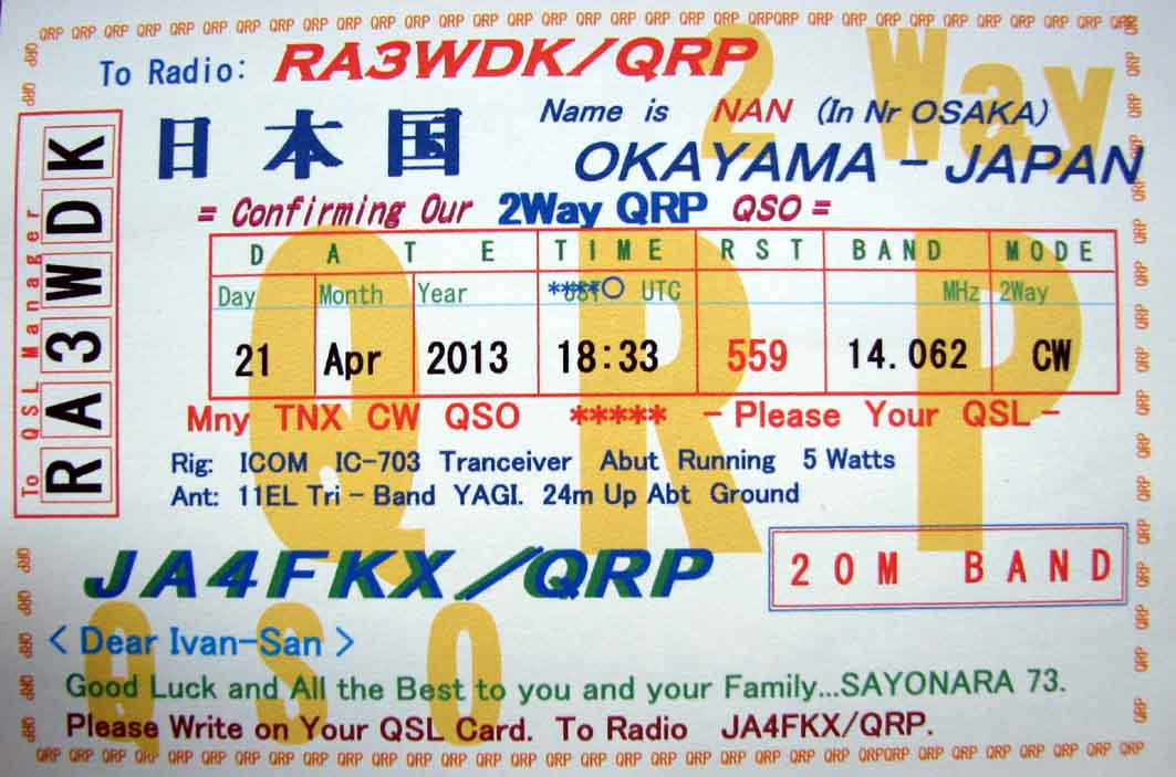
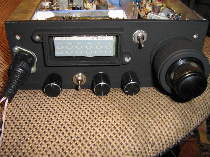
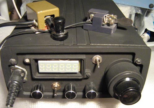
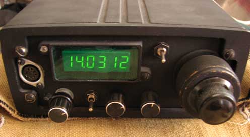
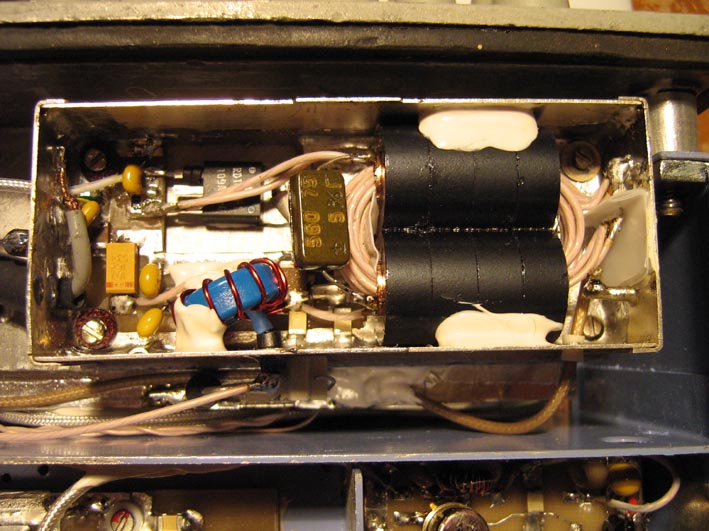
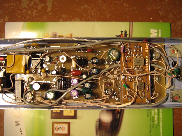
QRP Project QRP 20/40 m transceiver
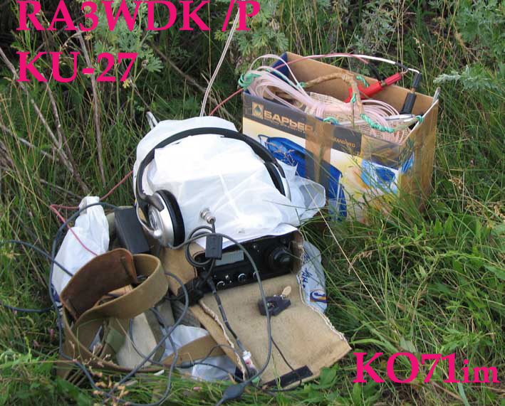
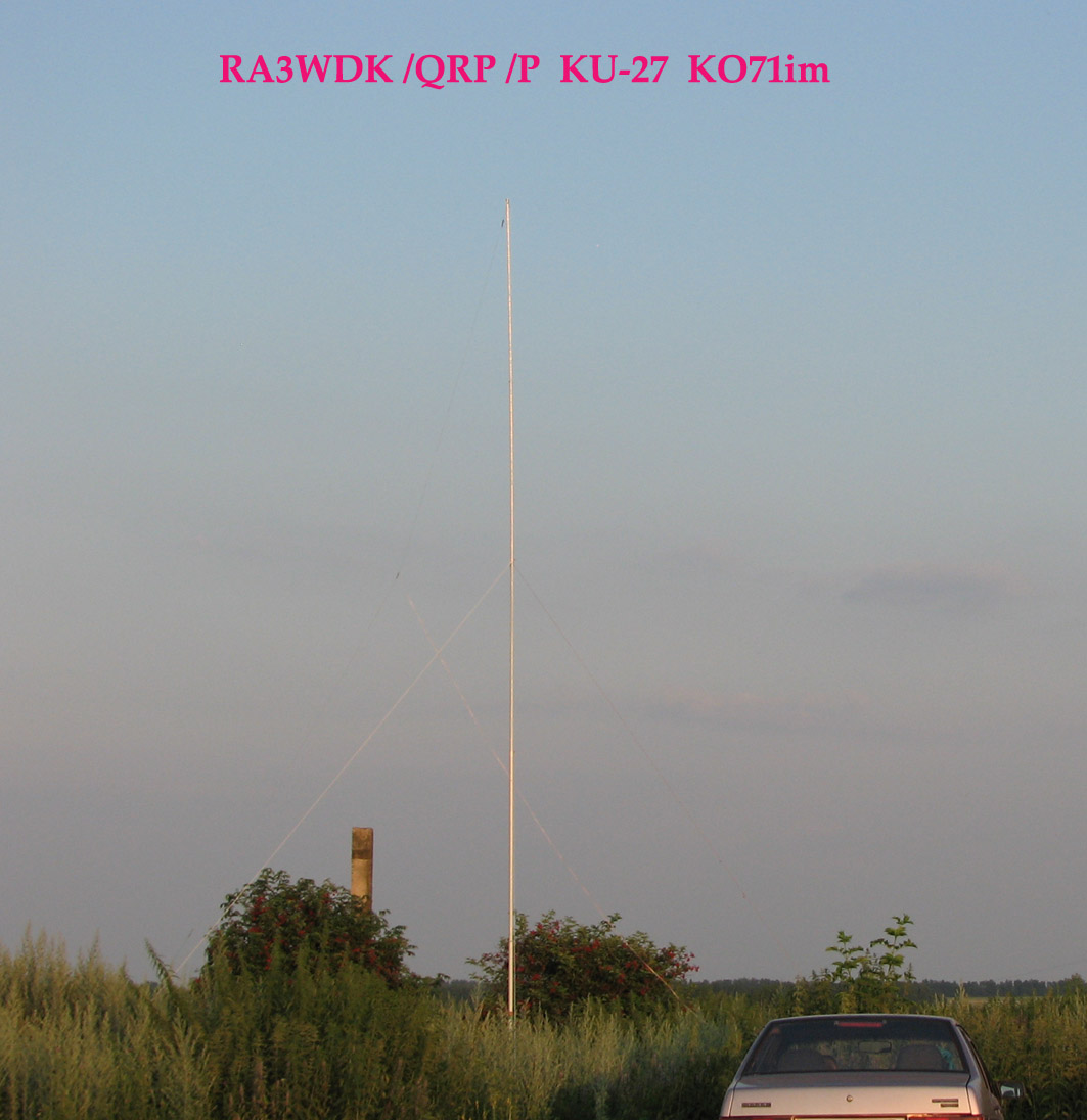
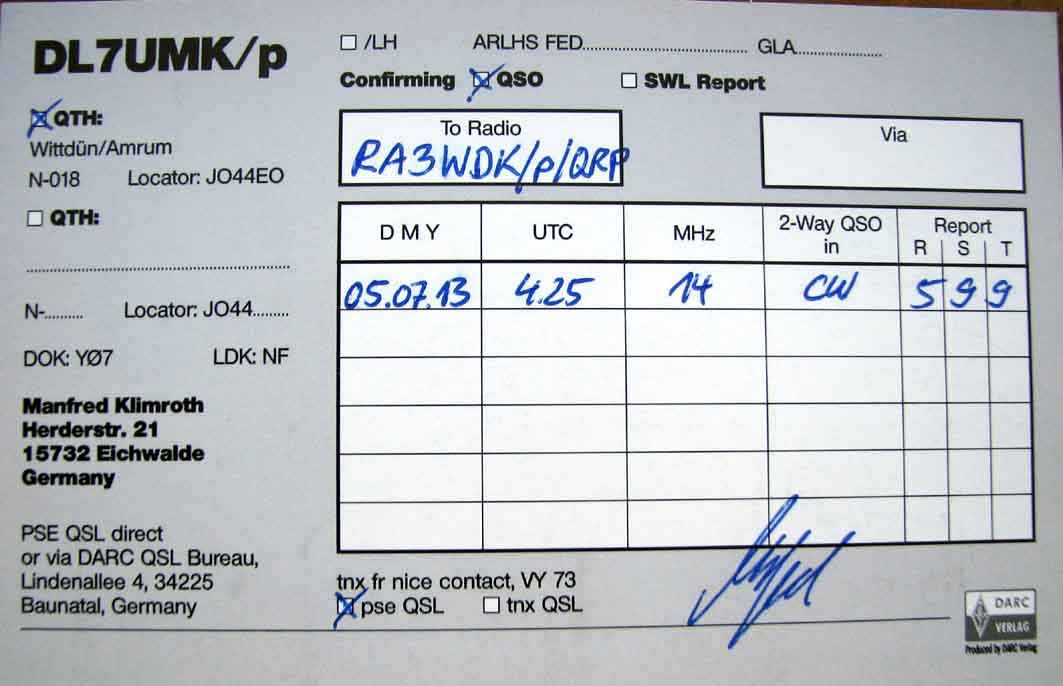
I like to operate /P/QRP with my portable equipment and antennas.
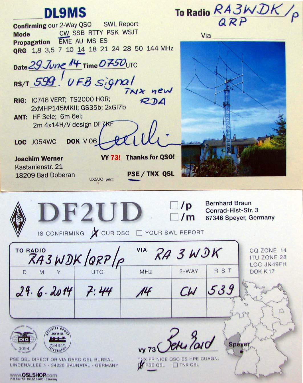
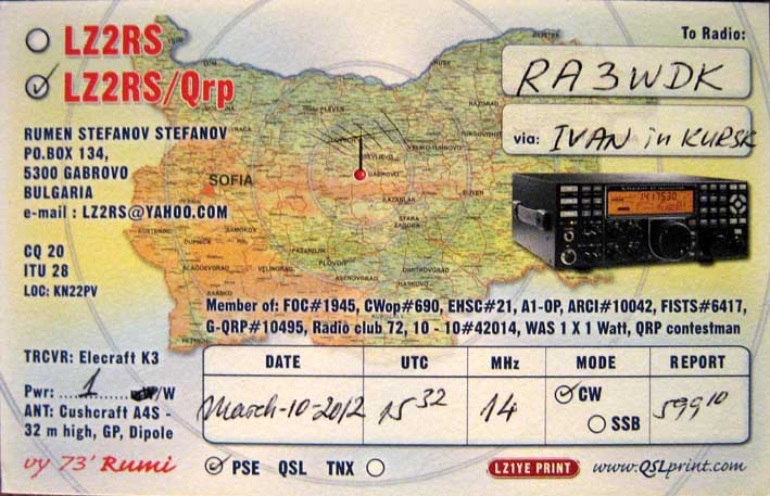
LZ2KSC / LZ2GX save my signal in QRP contest in 14 MHz
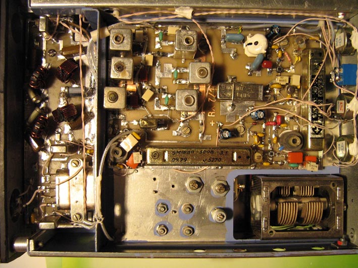
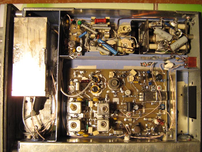
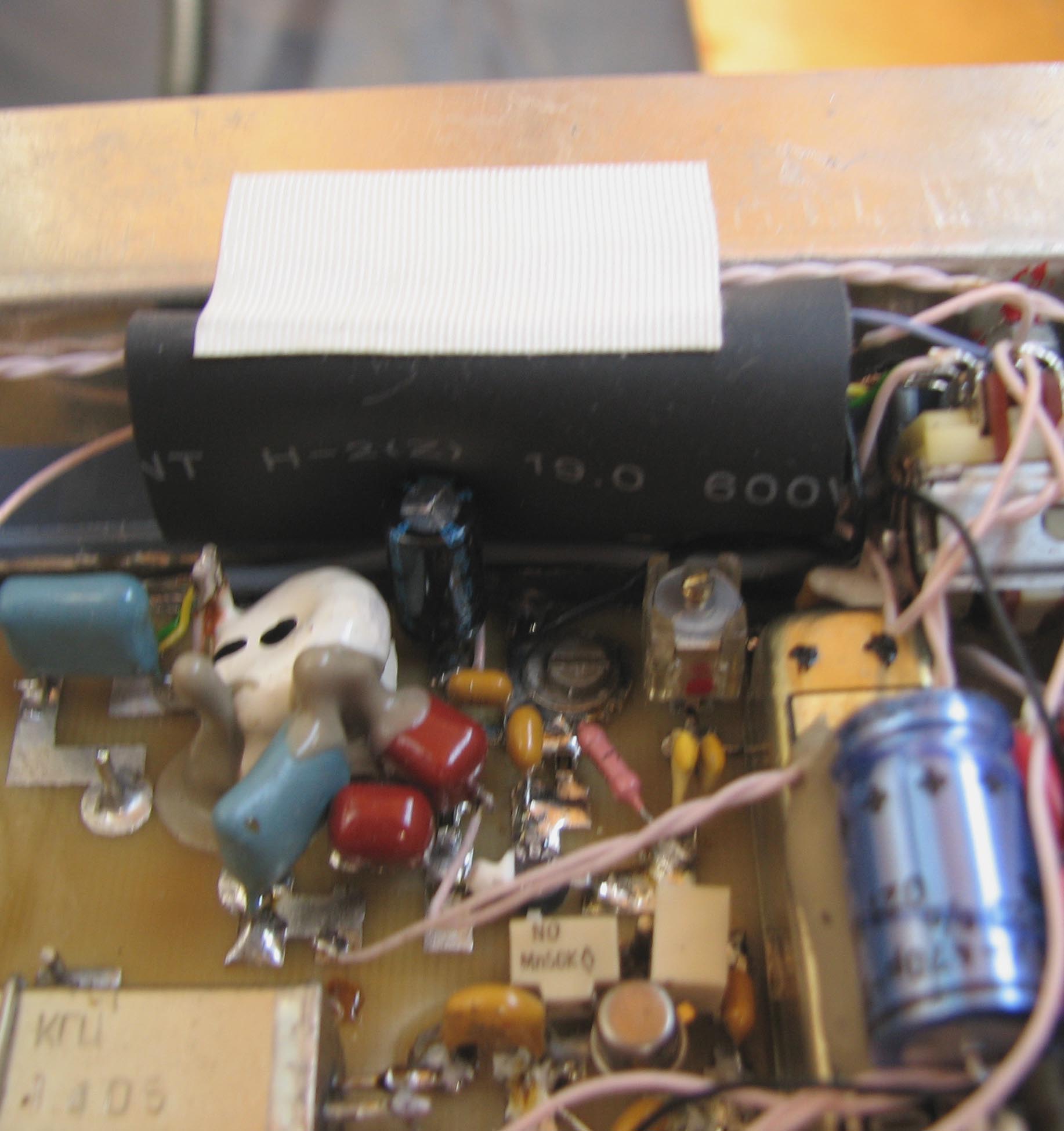
I had many QSO using a simple LW and coax-feed for my 144 MHz yagi. I use case from FM-301 FM radiostation. IF 500 kHz. PWR 5W (12V) / 8W (13,8V) (RD16HHF1) Energy performance : RX - 90/120 mA TX - 1,5 A (12V) / 2 A (13,8 V)
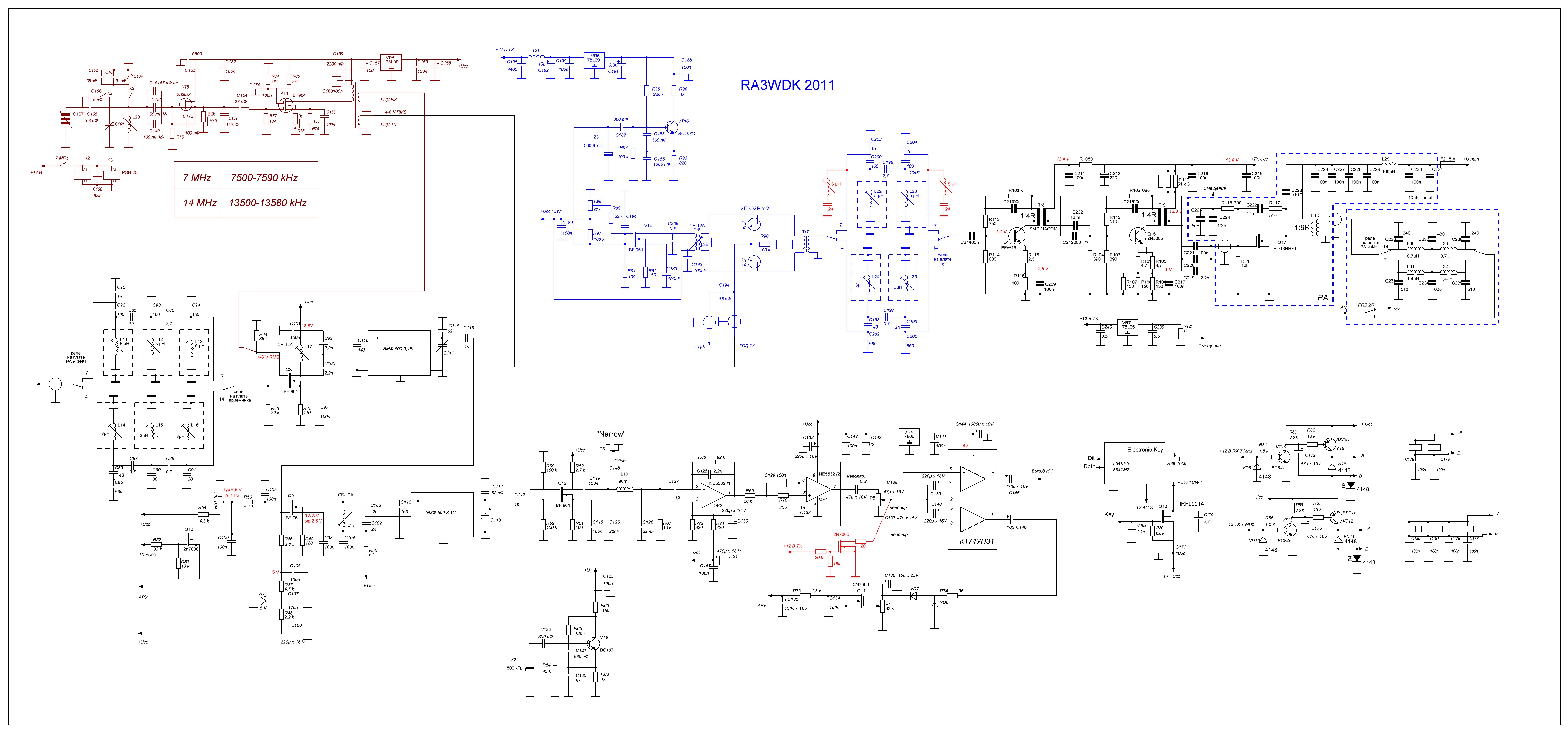
Full Schematic Circuit Diagram + modifications
SYMPLY CMOS ELECTRONIC CW KEYER
|
||||||||||||||||||||||||||||
|
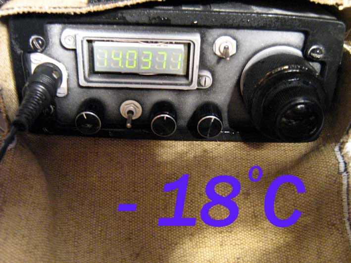
Low Temperature & High Humidity Test
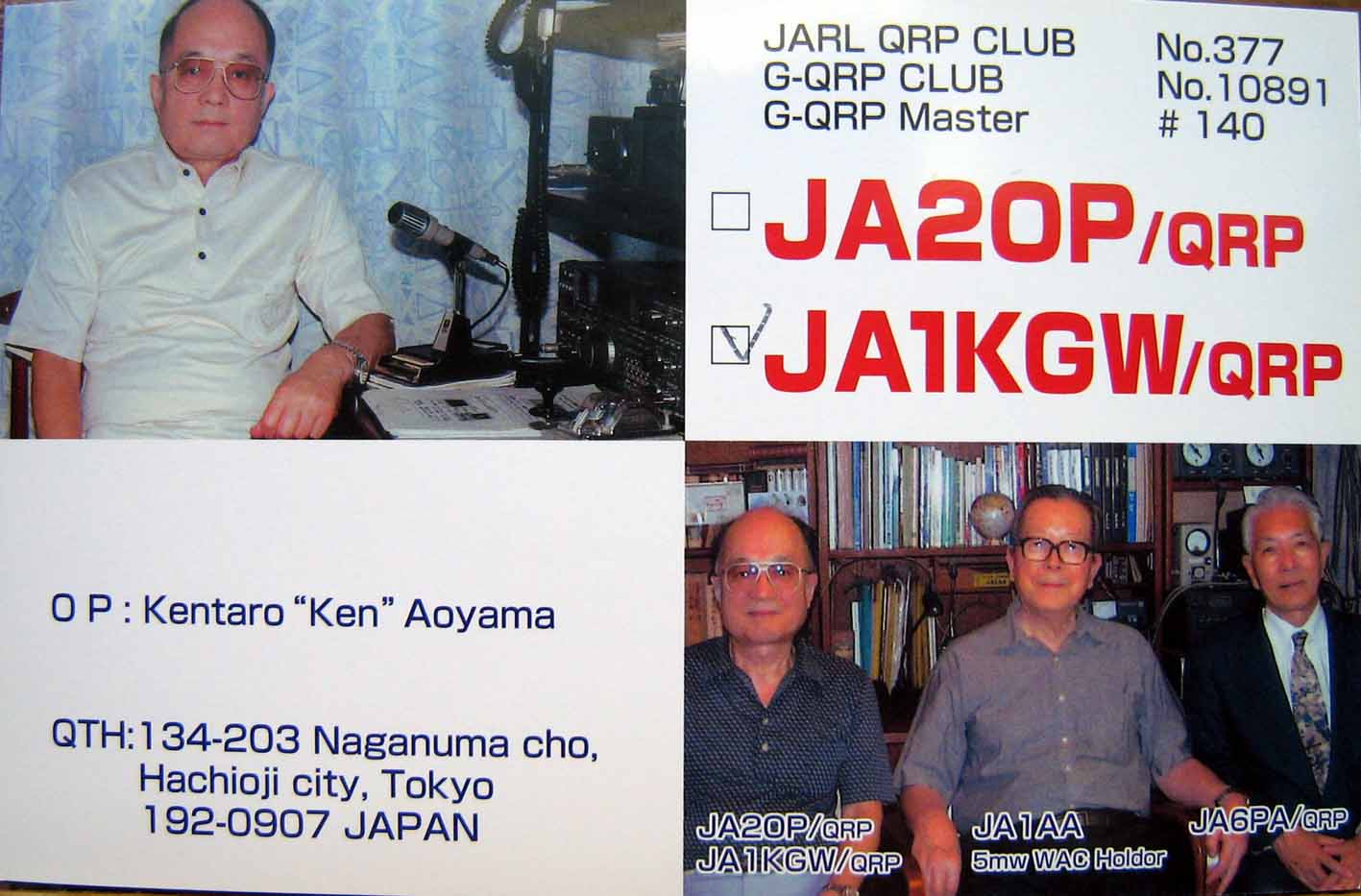
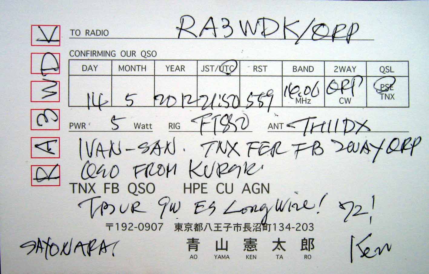
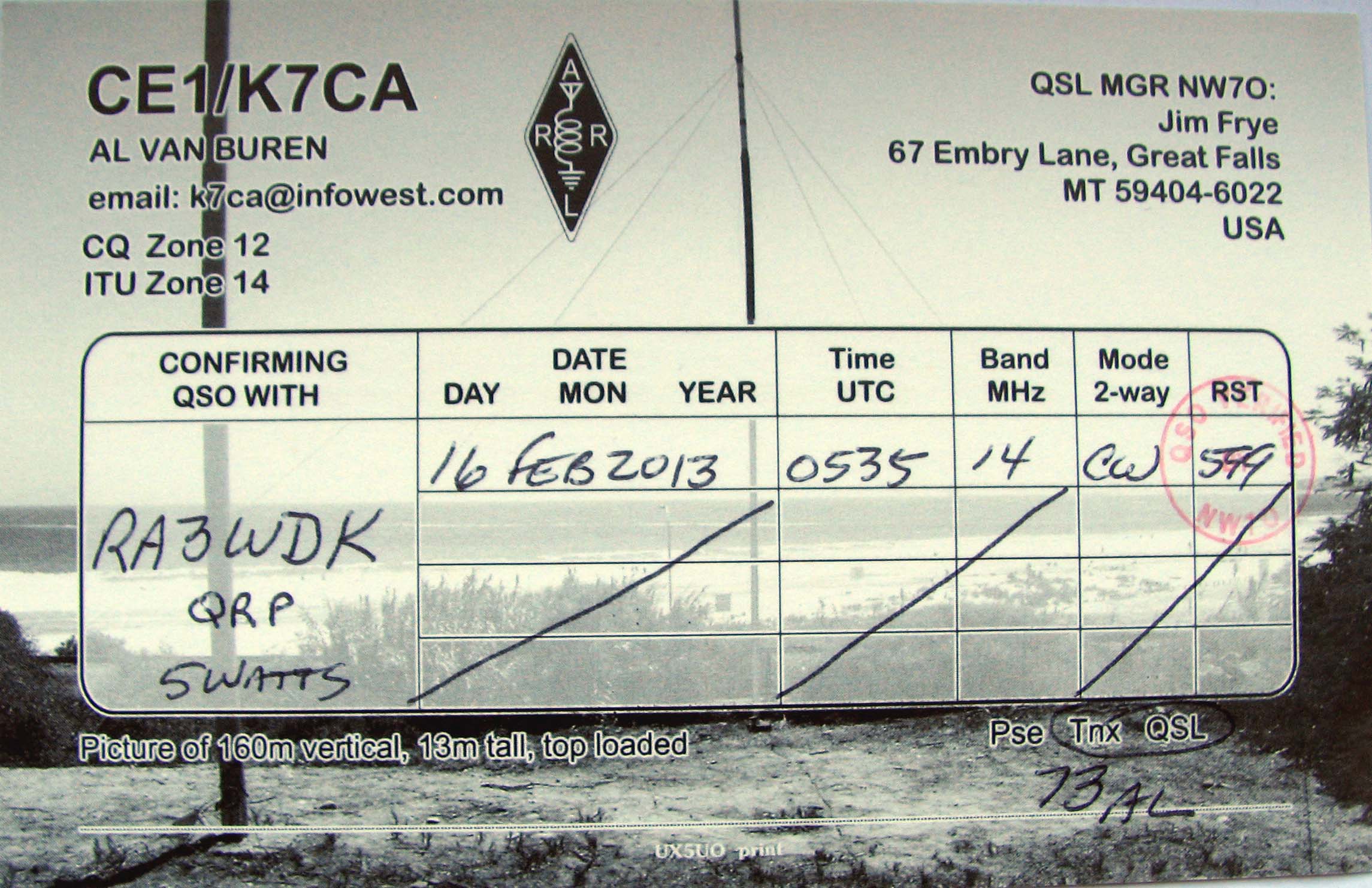
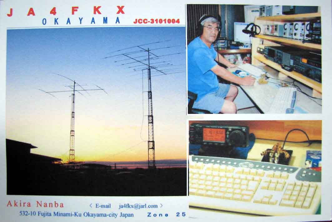
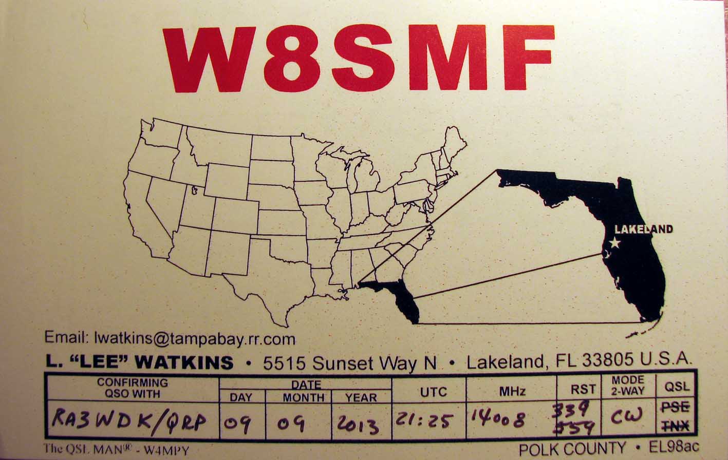
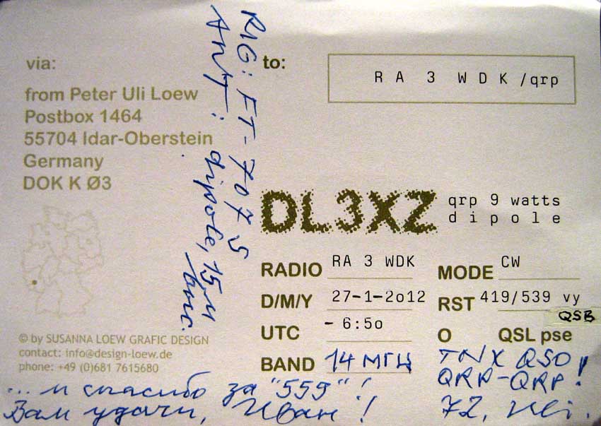
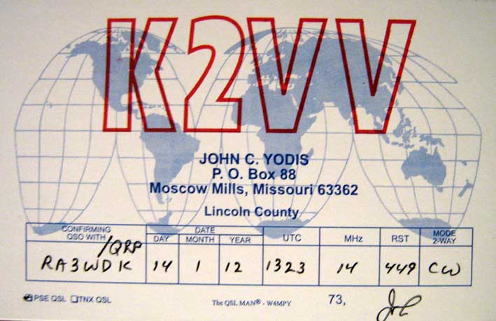
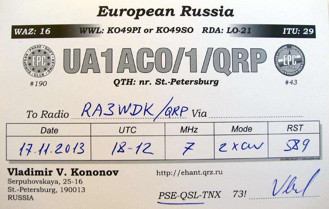
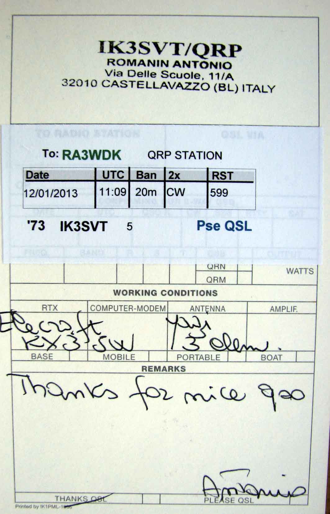
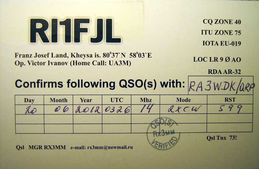
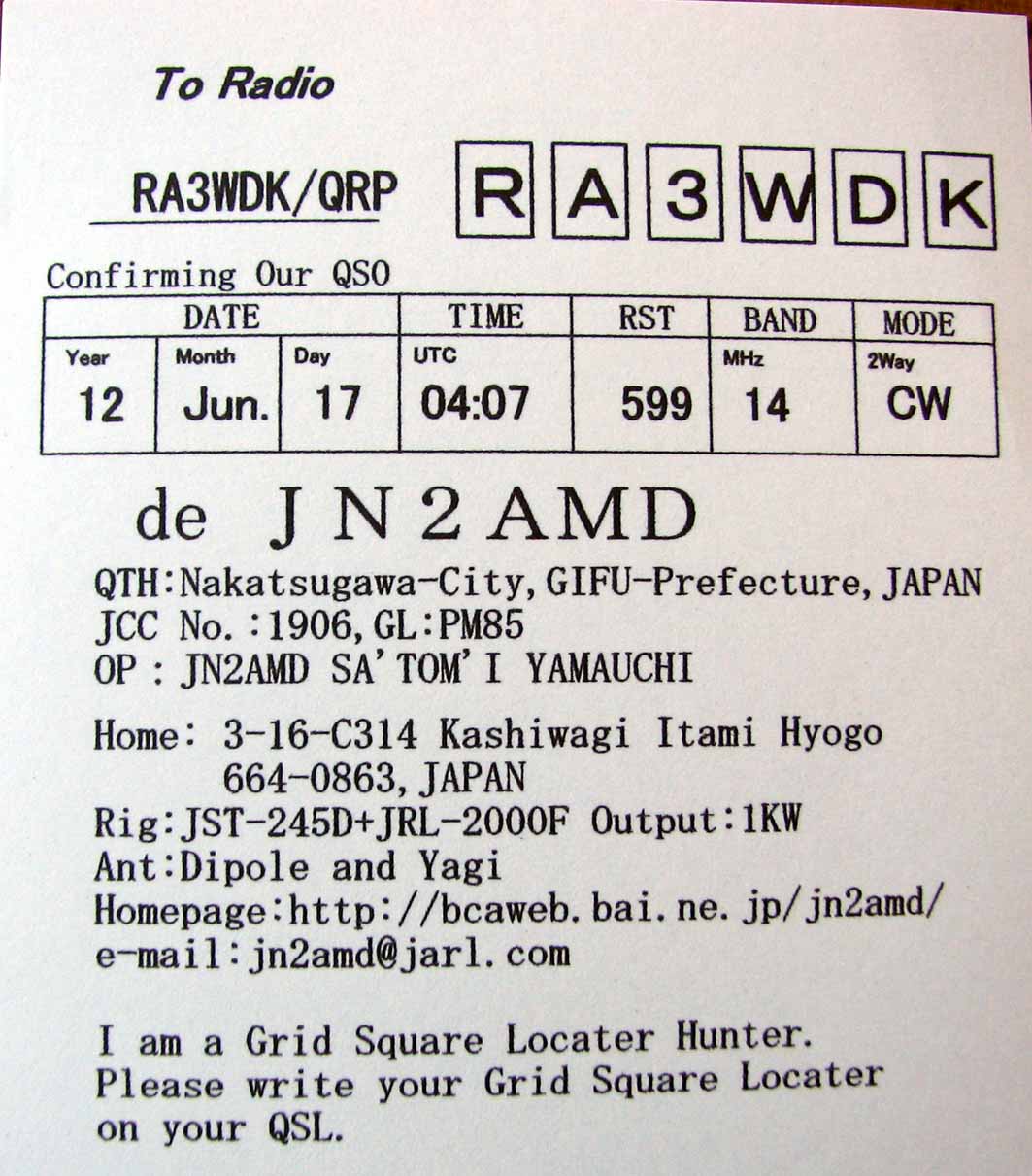
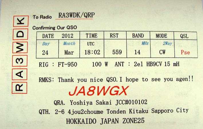
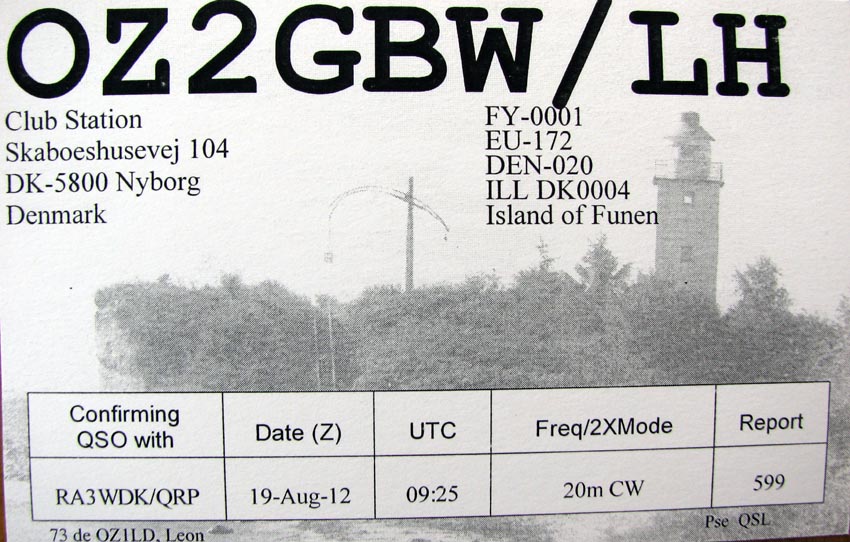
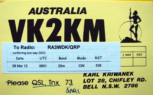
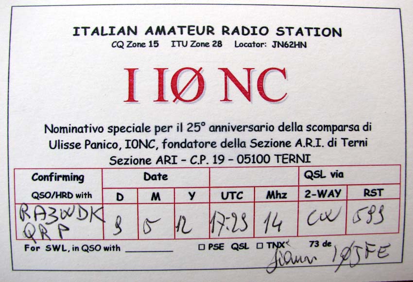
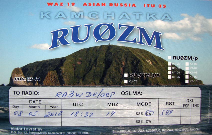
QRP/QRP QSOs and DX QSL
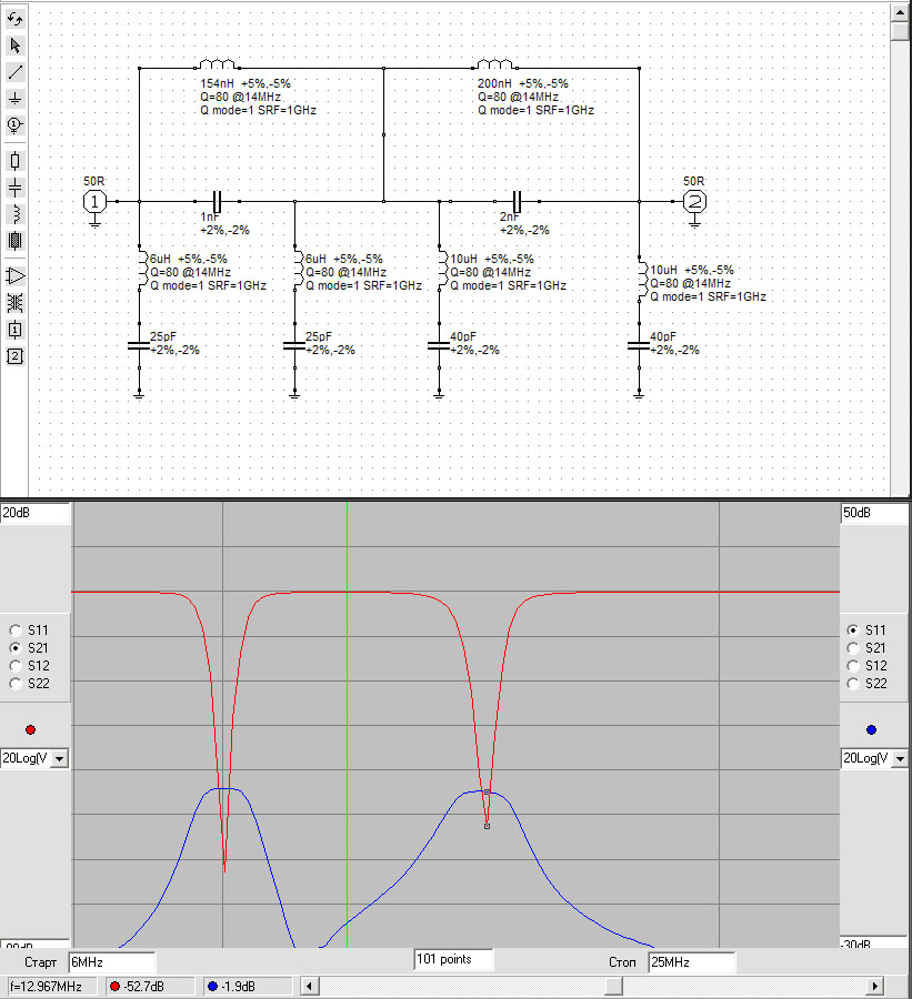
Modifications for improve Image Rejection ratio for low IF (500 kHz).
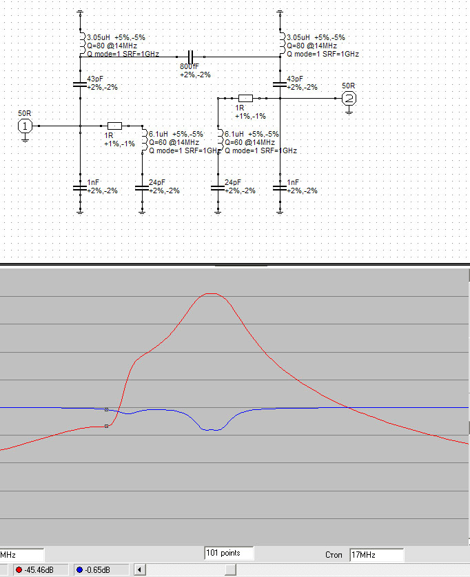
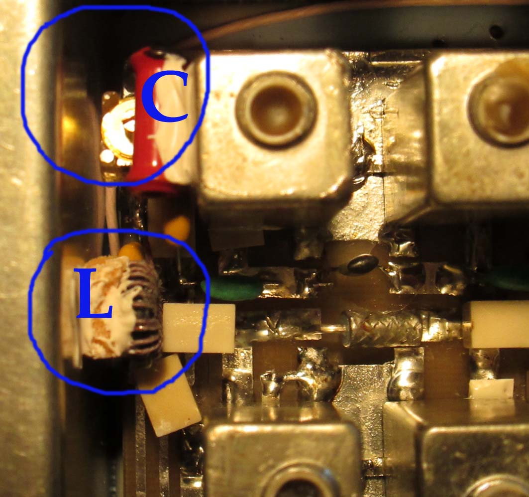
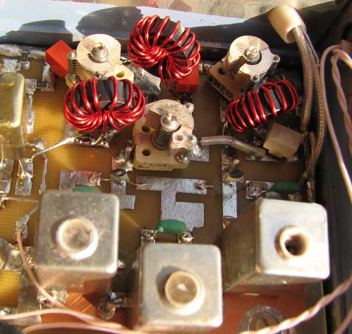
Modification BPF 14 MHz of RX
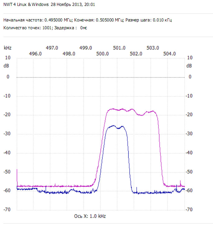
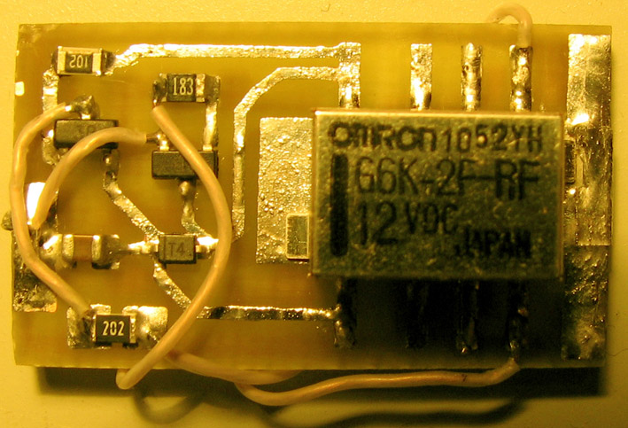
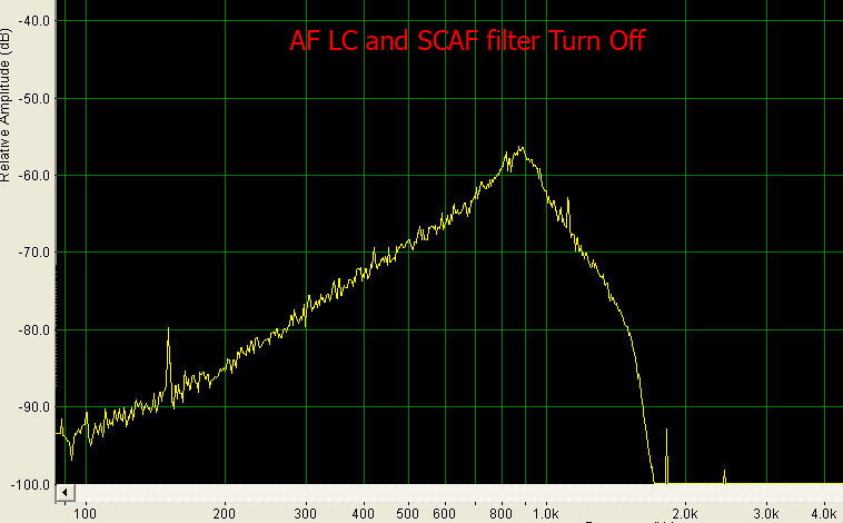
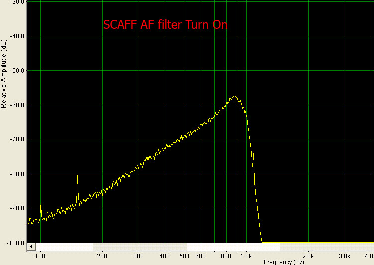
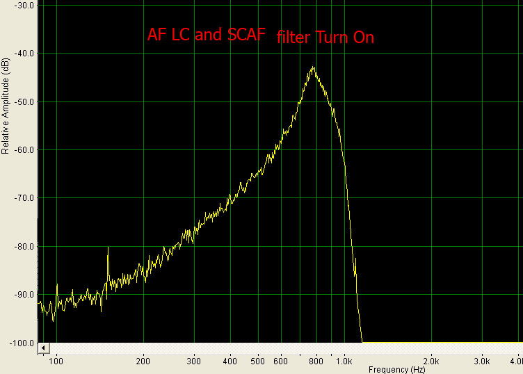
Switched-Capacitor AF Filter by MAX7400 You can modify your old transceivers
and receivers, you need only
Spectrum of AF output of receiver with different mode of operation: LC filter + Switched-Capacitor AF Filter by MAX7400
|
|||||||||||||||||||||||||||||
|
|
 |
||||||||||||||||||||||||||||


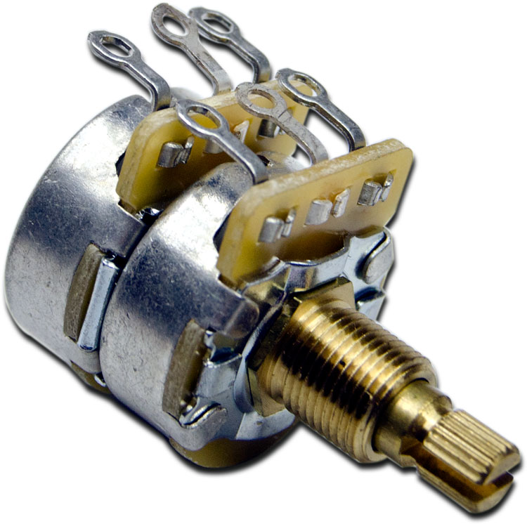 potentiometer and replace old potentiometer on AF or RF position. No
drilling front panel !
potentiometer and replace old potentiometer on AF or RF position. No
drilling front panel !